A Circuit:
Here is a circuit that can be used to control switchable electronic devices. Add some long leads to the PhotoResistor (CdS cell) and mount it pointed at your computer monitor. Use black card or a film cannister to control ambient light falling on the sensor. If you use this circuit to launch a model rocket, you must have a manual switching system built into the circuit and follow all model rocket flying safety procedures.
I hope to replace this "hand drawn" circuit with something a little more professional - but here is this one for now.
Supply Voltage - 6 Volts
IC1 - 4066 Quad Bilateral Switch
Q1 - NPN Transistor 2N3904 or Radio Shack #276-1617 (Image shows E,B,C from top)
PhotoResistor - CdS cell, Radio Shack #276-1657
VR1 - 100K variable resistor (Can be replaced with fixed resistor, depends on range of CdS cell, try 12K)
R1 - 330 Ohms
R2 - 27K Ohms
D1 - Diode, Radio Shack # 276-1122 (This diode controls current induced by the relay coil, the band marks the end connected to "+" in this circuit.)
A 5/6 volt relay with a coil resistance in the 60 - 300 Ohm range will work with this circuit.
Operation:
Adjust the variable resistor until the LED switches on when the CdS cell is exposed to light and off when the cell is dark. If you are using fixed resistors, experiment with different values until you find one that works.
Create a simple program in Qbasic (or any language you like) to create a controllable bright spot on the screen. To control the relay mount the CdS cell over the bright spot. You may have to experiment with VR1 to get the best results.
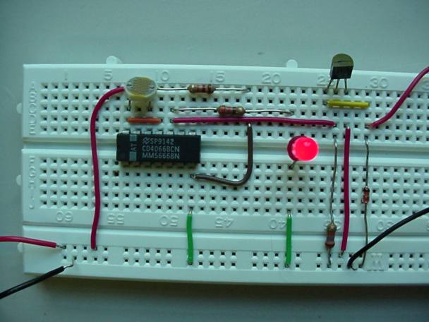
Image of Completed Circuit:
Note that VR1 has been replaced by a fixed resistor. For clarity I have the CdS cell mounted on the board.