Dos estrellas intermitentes

Un circuito que se puede utilizar a parpadear dos estrellas de Navidad alternativa se da aquí. The IC1 NE 555 is wired as an astable multivibrator here. El IC1 NE 555 se conecta como un multivibrador astable aquí. When there is a positive pulse from the output of IC1, the transistor Q1 conducts and the relay K1 gets activated. Cuando hay un pulso positivo de la salida de IC1, el transistor Q1 conduce y el relé K1 se activa. The lamp L2 connected via the N/O contact of the relay glows. La L2 lámpara conectada a través del contacto N / O del relé se ilumina. When the output pulse of the IC goes low, the Q1 goes OFF and the relay gets deactivated. Cuando el pulso de la salida de la IC pasa a BAJO, el Q1 se apaga y el relé se desactiva. Now the lamp L2 extinguishes and the lamp L1 connected via the N/C contact of the relay glows. Ahora, la L2 lámpara se apaga y la lámpara L1 conectado a través del contacto N / C del relé se ilumina. This cycle continues as long as there is power supply for the circuit. Este ciclo continúa como siempre y cuando exista la fuente de alimentación para el circuito. The timing of the lamps can be adjusted by varying the preset R2. La sincronización de las luces puede ser ajustado variando la R2 preestablecido.
Circuit diagram with Parts list. Diagrama del circuito con la lista de piezas.
two-star-flasher-circuit
Notes. Notas.
  • Assemble the circuit on  a good quality PCB. Montar el circuito en una buena calidad de PCB.
  • Power the circit from a 9V DC power supply. Poder circit de una fuente de alimentación 9V DC.
  • The preset R2 can be used to vary the timing of lights. El R2 preestablecidos se pueden utilizar para variar el tiempo de las luces.
  • The IC1 must be mounted on a holder. El IC1 debe montarse sobre un soporte.


Interruptor con CD4011

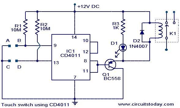
Un circuito del interruptor del tacto simple con CD4011 se da aquí. The IC CD4011 is wires as a flip flop here. El IC CD4011 está cables como un fracaso de tirón aquí. The 9, 13 pins of the IC works as the set and reset contacts respectively.CMOS ICs like 4011 require requires a very low current for controlling its gates. El 9, 13 pines del CI funciona como el sistema y el reajuste VA contactos respectively.CMOS como 4011 requieren requiere una corriente muy baja para el control de sus puertas. Since the pins 9 and 13 are connected to the positive via resistors R1 and R2, the logic gates of the ICs will be in high state. Puesto que los pines 9 y 13 están conectadas al positivo a través de resistencias R1 y R2, las puertas de la lógica de los circuitos integrados estará en estado alto. When we touch through the points A, B the gates of the IC will be closed and the output becomes low. Cuando tocamos a través de los puntos A, B, las puertas de la IC se cerrará y la salida es bajo. This switches ON the transistor Q1 and the relay gets activated. Esto cambia el transistor Q1 y el relé se activa. When we touch through the points C, D the gates again becomes high and switches the transistor OFF. Cuando tocamos por los puntos C, D de las puertas vuelve a ser alta y los interruptores del transistor. This makes the relay OFF. Esto hace que el apagado del relé. Thus by touching through the contact points A,B and C,D the appliance connected through the relay can be switched On and OFF. Así, al tocar a través de los puntos de contacto A, B y C, D el aparato conectado a través del relé se puede conectar y desconectar.
Circuit diagram with Parts list. Diagrama del circuito con la lista de piezas.
touch-switch-circuit-using-cd4011
Notes. Notas.
  • The circuit can be assembled on a general purpose PCB. El circuito se puede montar en un propósito general de PCB.
  • The circuit can be powered from 12V DC. El circuito puede funcionar con 12 V DC.
  • The IC must be mounted on a holder. El CI debe estar montado sobre un soporte.
  • The relay can be a 12 V, 200 Ohm SPDT relay. El relé puede ser de 12 V, 200 Ohm relé SPDT.


Interruptor de proximidad magnético

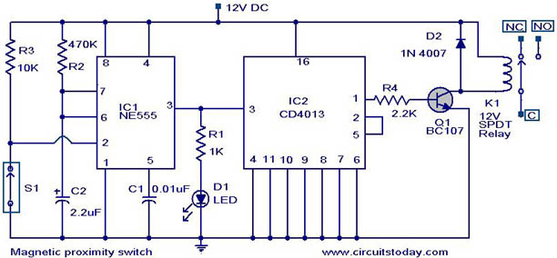
H ere es el diagrama del circuito de un interruptor de proximidad magnético que encuentra una gran cantidad de aplicaciones en el circuito fields.The muchos se basa en un interruptor de láminas magnético (S1) como el sensor de proximidad. A monostable multivibrator based on NE555 (IC1) and a toggle flip flop based on CD4013 (IC2) does the rest of the circuit. Un multivibrador monoestable basado en NE555 (IC1) y un fracaso de tirón de palanca sobre la base de CD4013 (IC2) hace el resto del circuito.
When a magnet is reached in proximity of S1 it closes to give a negative trigger at pin 2 of IC1.The output of IC1 goes high for a time determines by R2 and C2.This clocks the IC2 wired as a toggle flip flop.The output (pin 1 ) of IC2 goes high and the transistor Q1 is biased to ON.The relay is activated and so do the equipment connected to the relay.The LED D1 glows when IC1 is triggered. Cuando un imán que se llegó en la proximidad de S1 se cierra para dar un disparador negativo en el pin 2 de la salida de IC1 IC1.The va alto por un tiempo determina por R2 y C2.This relojes IC2 por cable como una salida flop.The tirón de palanca (terminal 1) de IC2 va alto y el transistor Q1 está sesgada para transmitir sucesivamente se activa y también lo hacen los equipos conectados a la relay.The D1 LED se ilumina cuando se activa IC1.
Circuit diagram with Parts list. Diagrama del circuito con la lista de piezas.
magnética-proximidad-switch.JPG
Notes. Notas.
  • Switch S1 can be a general purpose magnetic reed switch. El interruptor S1 puede ser un interruptor de láminas magnético de propósito general.
  • The equipment to control can be connected using NC,NO and C points of the relay according to the application. El equipo de control puede ser conectado a través de Carolina del Norte, NO y los puntos C del relé de acuerdo con la solicitud.
  • Use a 12 regulated power supply for powering the circuit. Utilice una fuente de alimentación regulada 12 para alimentar el circuito.


Led parpadeante a 220v

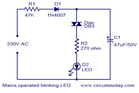
El esquema de una luz LED que puede ser operado de la red eléctrica se muestra aquí. The working of this circuit is as follows. El funcionamiento de este circuito es el siguiente. When mains power is switched ON the capacitor C2 charges through resistor R1 and diode D1. Cuando la red eléctrica se enciende los cargos condensador C2 a través del resistor R1 y el diodo D1. When the voltage across the capacitor becomes greater than 32V ( break over voltage of diac DB3) the diac conducts making  the LED blinks and  capacitor C1 discharges through the LED.This cycle repeats again and again . Cuando la tensión en el condensador es mayor que 32V (salto de más de tensión de DB3 cardíaca) el diac lleva a cabo haciendo que el LED parpadea y el condensador C1 descargas a través del ciclo LED.This repite una y otra vez.

mains operated blinking LED
Notes. Notas.
  • 230V is potentially dangerous , be very careful while handling this circuit. 230 es potencialmente peligroso, tener mucho cuidado al manipular este circuito.
  • The timing  of this circuit depends on resistor R1 and capacitor C1. El calendario de este circuito depende de la resistencia R1 y el condensador C1.


Pobador del 555

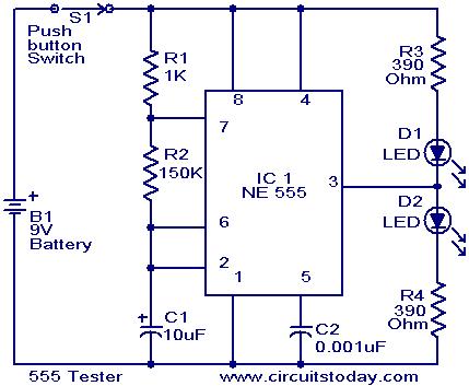
NE555 es un IC que es ampliamente utilizado en relojes y circuitos de control. A circuit for independent testing this IC is given here. Un circuito para las pruebas independientes de este IC se da aquí.
Here the NE555 is wired as an astable multivibrator. Aquí el NE555 se conecta como un multivibrador astable. When the push button switch S1 is pressed the LEDs D1 & D2 will flash alternatively. Cuando el interruptor pulsador S1 se pulsa el LED D1 y D2 parpadeará alternativamente. That is when output is high D2 will glow & when output is low D3 will glow. Es decir, cuando la producción es alta D2 se encenderá y cuando la salida es resplandor D3 baja. The rate of flashing will depend on components R1,R2 & C1. La tasa de parpadeo depende de los componentes R1, R2 y C1.
When push button S1 is pressed,C1 will start charging through R1&R2.When the voltage across C1 rises above 2 of 3 is the supply voltage the internal Flip Flop toggles . Cuando pulse el botón se pulsa S1, C1 comenzará a cargarse a través de R1 y R2.When el voltaje a través C1 se eleva por encima del 2 de 3 es la tensión de alimentación interna de la Flip Flop cambia. The pin 7 becomes low & C1 starts discharging. El pin 7 pasa a ser bajo y C1 comienza la descarga. When the voltage across C1 goes below 1of 3 of supply voltage the internal Flip Flop resets & pin7 goes high. Cuando el voltaje a través de C1 desciende por debajo de 1 de 3 de tensión de alimentación del interior restablece Flip Flop y Pin7 pasa a ALTO. The C1 again starts charging.All this will take place if the IC is healthy. El nuevo C1 comienza charging.All esta se llevará a cabo si la IC es saludable.
According to the frequency of this charging & discharging D1&D2 will flash. De acuerdo a la frecuencia de esta carga y que descarga D1 y D2 flash. From these observations we can conclude that IC NE555 is faulty or not . A partir de estas observaciones podemos concluir que la CI NE555 es culpable o no.
Circuit diagram with Parts list. Diagrama del circuito con la lista de piezas.
555-tester-circuit.jpg
Notes. Notas.
  • Assemble the circuit on a good quality PCB or common board. Montar el circuito en una buena calidad de PCB o placa común.
  • Power the circuit from a 9V radio battery. Alimentar el circuito con una batería de 9V de radio.
  • If D1 and D2 flashes on the pressing of S1,we can assume that the IC is working. Si D1 y D2 parpadea en el prensado de S1, podemos suponer que la IC está trabaj

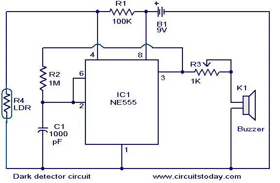
Detector de oscuridad

El circuito detector de oscuro se muestran se pueden utilizar para producir una alarma sonora cuando la luz dentro de una habitación se apaga. The circuit is build around timer IC NE555.A general purpose LDR is used for sensing the light. El circuito se desarrolla en torno temporizador IC propósito NE555.A general LDR se utiliza para detectar la luz. When proper light is falling on the LDR its resistance is very low. Cuando la luz adecuada está cayendo sobre la LDR su resistencia es muy baja. When there is no light the LDR resistance increases. Cuando no hay luz que aumenta la resistencia LDR. At this time the IC is triggered and drives the buzzer to produce an alarm sound. En este momento el CI se dispara y conduce el timbre para producir un sonido de alarma. If a transistor and relay is connected at the output (pin3) of IC1 instead of the buzzer, electrical appliances can be switched according to the light. Si un transistor y el relé está conectado a la salida (pin 3) de IC1 en lugar del timbre, los aparatos eléctricos se puede cambiar de acuerdo a la luz.
Circuit diagram with Parts list. Diagrama del circuito con la lista de piezas.
oscuro detector _circuit.JPG


Leds a 220v

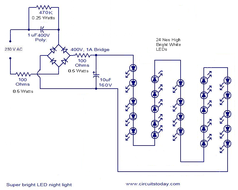
Esta es una versión modificada del circuito Super brillante LED de luz de la noche aquí publicados. This circuit is submitted by Mr. Seetharaman and its full credit goes to him. Este circuito está presentado por el Sr. Seetharaman y su crédito total se acerca a él.
This is the circuit of a well tried and reliable 230 Volt AC mains operated 24 LEDs (super bright 50mA LEDs). Este es el circuito de un pozo probado y fiable red de 230 voltios de CA funciona las 24 LED (LED brillante estupendo 50 mA). While practically compare the brightness between this circuit and 11watts tube, the LED light is much better. Si bien prácticamente comparar el brillo entre este circuito y el tubo de 11watts, la luz LED es mucho mejor. The layout is made in such a way, you get uniform illumination. La distribución se hace de tal manera, se obtiene una iluminación uniforme. A photograph of the cicuit is also given in this post. Una fotografía de la cicuit también se da en este post.
mains led