NE555 es un IC que es ampliamente utilizado en relojes y circuitos de control. A circuit for independent testing this IC is given here. Un circuito para las pruebas independientes de este IC se da aquí.
Here the NE555 is wired as an astable multivibrator. Aquí el NE555 se conecta como un multivibrador astable. When the push button switch S1 is pressed the LEDs D1 & D2 will flash alternatively. Cuando el interruptor pulsador S1 se pulsa el LED D1 y D2 parpadeará alternativamente. That is when output is high D2 will glow & when output is low D3 will glow. Es decir, cuando la producción es alta D2 se encenderá y cuando la salida es resplandor D3 baja. The rate of flashing will depend on components R1,R2 & C1. La tasa de parpadeo depende de los componentes R1, R2 y C1.
When push button S1 is pressed,C1 will start charging through R1&R2.When the voltage across C1 rises above 2 of 3 is the supply voltage the internal Flip Flop toggles . Cuando pulse el botón se pulsa S1, C1 comenzará a cargarse a través de R1 y R2.When el voltaje a través C1 se eleva por encima del 2 de 3 es la tensión de alimentación interna de la Flip Flop cambia. The pin 7 becomes low & C1 starts discharging. El pin 7 pasa a ser bajo y C1 comienza la descarga. When the voltage across C1 goes below 1of 3 of supply voltage the internal Flip Flop resets & pin7 goes high. Cuando el voltaje a través de C1 desciende por debajo de 1 de 3 de tensión de alimentación del interior restablece Flip Flop y Pin7 pasa a ALTO. The C1 again starts charging.All this will take place if the IC is healthy. El nuevo C1 comienza charging.All esta se llevará a cabo si la IC es saludable.
According to the frequency of this charging & discharging D1&D2 will flash. De acuerdo a la frecuencia de esta carga y que descarga D1 y D2 flash. From these observations we can conclude that IC NE555 is faulty or not . A partir de estas observaciones podemos concluir que la CI NE555 es culpable o no.
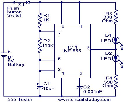
Circuit diagram with Parts list. Diagrama del circuito con la lista de piezas.
Notes. Notas.
- Assemble the circuit on a good quality PCB or common board. Montar el circuito en una buena calidad de PCB o placa común.
- Power the circuit from a 9V radio battery. Alimentar el circuito con una batería de 9V de radio.
- If D1 and D2 flashes on the pressing of S1,we can assume that the IC is working. Si D1 y D2 parpadea en el prensado de S1, podemos suponer que la IC está trabaj