La parte principal de este circuito de timbre dos temporizador NE555 ICs.When alguien presiona el interruptor S1 momentáneamente, el altavoz emite un tono de timbre, siempre y cuando el período de tiempo del multivibrador monoestable construido alrededor de IC1.
When the switch S1 pressed, IC1 is triggered at its pin 2 and output pin 3 goes high for a time period previously set by the values of POT R4 and POT R5.When the output ofIC1 goes high it resets IC2 and it starts to oscillate to make a bell sound through the speaker.The IC2 is configured as an astable multivibrator whose oscillation frequency can be varied with the help of POT R5.By adjusting the values of R4 & R5, modifications on the tone are possible. Cuando se pulsa el interruptor S1, IC1 se activa en su pin 2 y pin de salida 3 va alto para un período de tiempo previamente fijado por los valores de POT R4 y R5.When POT la salida ofIC1 pasa a ALTO que restablece IC2 y comienza a oscilar a hacer un sonido de la campana a través de la IC2 speaker.The se configura como un multivibrador astable cuya frecuencia de oscilación se puede variar con la ayuda de POT R5.By ajustando los valores de R4 y R5, modificaciones en el tono son posibles.
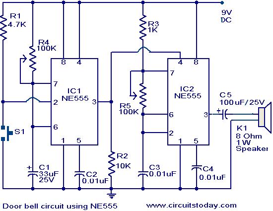
Circuit diagram with Parts list. Diagrama del circuito con la lista de piezas.
Notes. Notas.
- The circuit has to assembled on a good quality PCB or common board. El circuito tiene que montado en una buena calidad de PCB o placa común.
- The IC1 & IC2 has to be mounted on IC holders. El IC2 IC1 y tiene que ser montado en los titulares de la CI.
- Power the circuit from a 9V battery or 9V DC power supply. Alimentar el circuito con una batería de 9V o fuente de alimentación 9V DC.
- Switch S1 is push button switch. El interruptor S1 se interruptor de botón.