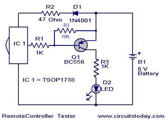
Este es un simple circuito probador remoto controlador basado en el sensor infrarrojo del IC TSOP 1738. When the IR waves fall on the sensor it output changes to low state.This makes the transistor Q1 ON and LED will blink according to the code contained in the signal.So for press of each button the LED blinks in different ways.This is a good indication of the working of remote.The diode D1drops 0.7 V to give the IC ~ 5V supply from the available 6V .R2 is a current limiting resistance. Cuando las ondas de infrarrojos caer en el sensor de la salida cambia a estado.Esta baja hace que el transistor Q1 y el LED parpadea de acuerdo con el código contenido en el signal.So para la prensa de cada botón el LED parpadea en ways.This diferentes es un buen indicador del funcionamiento del diodo remote.The D1drops 0,7 V para dar el CI ~ 5V 6V de la disposición. R2 es una resistencia de limitación de corriente.
Circuit Diagram with Parts List . Diagrama de circuito con la lista de piezas.

Notes . Notas.
- Use a 6V battery to power up the circuit. Utilice una batería de 6V para alimentar el circuito.
- This circuit can be used to test remotes operating in the 38Khz carrier frequency.Almost all remotes fall into this category so no problem. Este circuito puede ser utilizado para probar mandos a distancia que operan en la frecuencia de 38 Khz frequency.Almost transportista toda la caída mandos a distancia en esta categoría no hay problema.