 |
| USB powered AA charger schematic. Alimentado por USB cargador AA esquemática. |
TR1 is a thermistor that is in direct contact with the cells being charged. TR1 es un termistor que está en contacto directo con las células está cargando. It has a resistance of 10kΩ at 25°C (77°F), which varies inversely with temperature by about 3.7% for every 1C° (1.8F°). Tiene una resistencia de 10 k a 25 ° C (77 ° F), que varía inversamente con la temperatura en alrededor de 3,7% por cada grado 1C (1.8F °). R3 and TR1 form a voltage divider whose value is applied to the inverting input (pin 2, Vtmp ). TR1 y R3 forman un divisor de tensión cuyo valor se aplica a la entrada inversora (pin 2, Vtmp). At a temperature of 20°C (68°F), TR1 is about 12kΩ, which makes Vtmp about 1.76V. A una temperatura de 20 ° C (68 ° F), TR1 se trata de 12kΩ, lo que hace Vtmp acerca de 1.76V.
Once the cells are fully charged, the charge current will literally go to waste, in the form of heat. Una vez que las células están completamente cargadas, la corriente de carga, literalmente, ir a perder, en forma de calor. As the cell temperature rises, TR1's resistance drops. A medida que aumenta la temperatura de la célula, TR1 cae resistencia. At 33°C (91°F), the resistance will be about 7.4kΩ, which makes Vtmp about 1.26V, which equals the Vref voltage. A los 33 ° C (91 ° F), la resistencia será de unos 7.4kΩ, lo que hace Vtmp sobre 1.26V, lo que equivale a la tensión Vref.
 | |
| Battery voltage versus time. Voltaje de la batería en función del tiempo. The cells are full when the voltage peaks, and the charger shuts off shortly thereafter. Las células se completa cuando los picos de voltaje, y el cargador se apaga poco después. |
Z1b is the other comparator on the LM393 chip, and a close look at the schematic reveals that it's performing the same comparison as Z1a. Z1B es el comparador de otros en el chip LM393, y ver de cerca el esquema revela que se trata de realizar la misma comparación que Z1A. Instead of driving the charging transistor however, it drives an LED that indicates that charging is in progress. En vez de conducir el transistor de carga sin embargo, las unidades de un LED que indica que la carga está en progreso. R6 limits current to the LED to about 10mA. R6 limita la corriente para el LED a cerca de 10 mA. By running the LED from its own comparator (which is on the chip whether we use it or not), the LED current has no effect on Vref . Al ejecutar el LED de su propio comparador (que está en el chip si usamos o no), el LED actual no tiene ningún efecto sobre la Vref.
Finally, C1 is there to ensure that charging starts when a pair of cells is inserted. Por último, C1 está allí para garantizar que la carga se inicia cuando un par de células se inserta. With no cells in place and the charger off, C1 has about 1.9V across it (5V - 0.7V - Vref). Sin las células en el lugar y el cargador apagado, C1 tiene alrededor de 1.9V a través de ella (5V - 0.7V - Vref). As soon as the second of two cells is inserted, the positive side of C1 is suddenly forced down to the battery voltage (about 2.4V). Tan pronto como la segunda de las dos células se inserta, el lado positivo de C1 de repente forzada hasta el voltaje de la batería (alrededor de 2,4 V). This immediately forces the negative side 1.9V lower than this, to about 0.5V. Esto inmediatamente las fuerzas de la 1.9V lado negativo menor que esto, a cerca de 0.5V. Since this is connected to Vref , Z1a's output goes low, causing charging to start. Dado que este se conecta a Vref, la salida va Z1A baja, causando la carga para empezar. After a few milliseconds, C1 adjusts to the new voltage difference imposed by R1, R2, and R4 on one side and the cells on the other, and no longer affects the circuit. Después de unos pocos milisegundos, C1 se ajusta a la nueva diferencia de tensión impuesta por R1, R2 y R4 por un lado y las células de la otra, y ya no afecta el circuito.
Construction Construcción
The circuit is best built on a printed circuit board. El circuito es el mejor construido sobre una placa de circuito impreso. Refer to my article on the subject, Making Excellent Printed Circuit Boards . Véase mi artículo sobre el tema, excelente Hacer tarjetas de circuito impreso . Here is the printed circuit layout: Aquí está el diseño de circuitos impresos: |
| Copper side. Cobre lado. Actual size is 3.8" x 1.2" (9.7cm x 3.0cm). Tamaño real es de 3.8 "x 1.2" (9.7cm x 3.0cm). Click to enlarge. Haga click para ampliar. |
 |
| Component placement diagram. Componente diagrama de la colocación. Click to enlarge. Haga click para ampliar. |
Transistor Q1 is mounted on a small heatsink. El transistor Q1 está montado sobre un disipador pequeño. First bend the leads back 90° just where they start to narrow. En primer lugar doblar la lleva de nuevo a 90 ° justo donde comienzan a estrecharse. Don't bend them too sharply or they might break. No doble demasiado fuerte o que podría romper. Insert Q1 into its lead holes, and slide the heatsink underneath. Inserte Q1 en sus agujeros de plomo, y deslice el disipador de calor por debajo. Hold everything in place with a clamp while soldering the leads. Mantenga todo en su lugar con una pinza de soldar los cables al mismo tiempo. With the clamp still in place, drill the hole for the heatsink bolt. Con la pinza todavía en su lugar, perfore el agujero para el tornillo del disipador de calor.
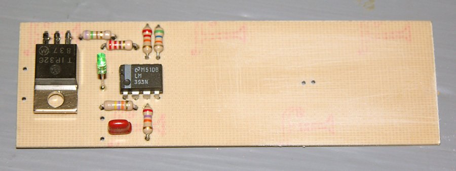 |
| Charger with all electronic components installed. Cargador con todos los componentes electrónicos instalados. Note that there is space under Q1 for the heatsink. Tenga en cuenta que no hay espacio disponible en el Q1 para el disipador de calor. The board area where the battery holder will go has been scuffed up to aid adhesion. El área del tablero donde el soporte de la batería se va ha rayado a la ayuda de adhesión. |
Before installing the holder, remove a ¼" long section of the centre divider to make room for the thermistor. Also solder some leads to the cell holder terminals. Glue the holder in place on the circuit board, flush with the sides and ends of the board. When the glue has dried, drill through the TR1 holes in the board to make matching holes in the battery holder. If you did everything carefully, these two holes should be right on the centre line, where you removed the section of divider. Antes de instalar el soporte, quitar un ¼ "larga sección del divisor central para hacer lugar para el termistor. También soldadura algunas pistas a los terminales celulares titular. Pegue el soporte en su lugar en el circuito, al ras con los lados y extremos de la bordo. Cuando el pegamento se haya secado, perfore a través de la TR1 agujeros en el tablero para hacer los agujeros correspondientes en el soporte de la batería. Si has hecho todo con cuidado, estos dos agujeros se deben a la derecha en la línea central, donde se ha extraído la sección del divisor.
Insert the thermistor through the holes, and then put a pair of AA cells in the holder. Inserte el termistor a través de los agujeros, y luego poner un par de pilas AA en el soporte. From the copper side, push up on the thermistor so it is in firm contact with the cells, and then solder it in place. Desde el lado de cobre, empuje hacia arriba en el termistor lo que está en firme contacto con las células, y luego soldar en su lugar. Then remove the cells, and connect the battery holder leads to the holes marked B+ and B- on the placement diagram. A continuación, retire las células, y conecte el soporte de la batería lleva a los agujeros marcados B + y B-en el diagrama de la colocación.
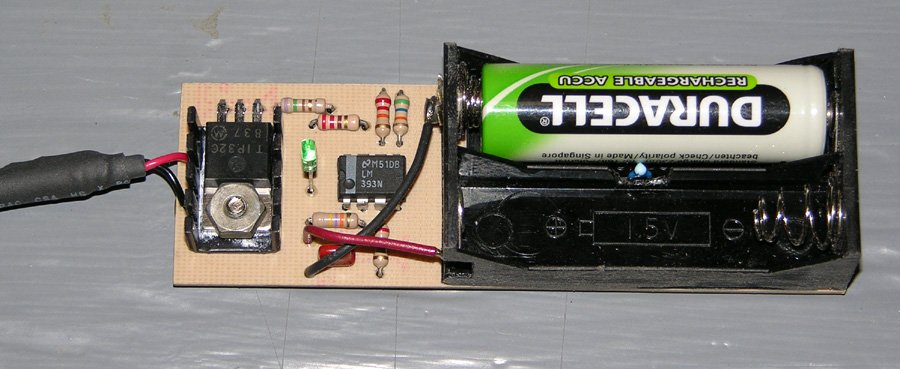 |
| The completed charger with one cell in place. El cargador completa con una célula en su lugar. The 2-cell holder was made by cutting the outer positions off of a 4-cell holder. El titular de dos de las células se realizó mediante la reducción de las posiciones externas fuera de un titular de 4 celdas. Notice how the thermistor is installed so as to make physical contact with the cells being charged. Observe cómo el termistor se instala con el fin de hacer contacto físico con las células está cargando. A small heatsink keeps Q1 cool. Un disipador de calor pequeño Q1 mantiene fresco. |
Testing Pruebas
Before connecting the charger to a power source, inspect your work carefully. Antes de conectar el cargador a la corriente eléctrica, inspeccione cuidadosamente su trabajo. Be sure all the components are oriented correctly (specifically Q1, LED1, Z1, and the battery holder). Asegúrese de que todos los componentes tienen la orientación correcta (específicamente Q1, LED1, Z1, y el soporte de la batería).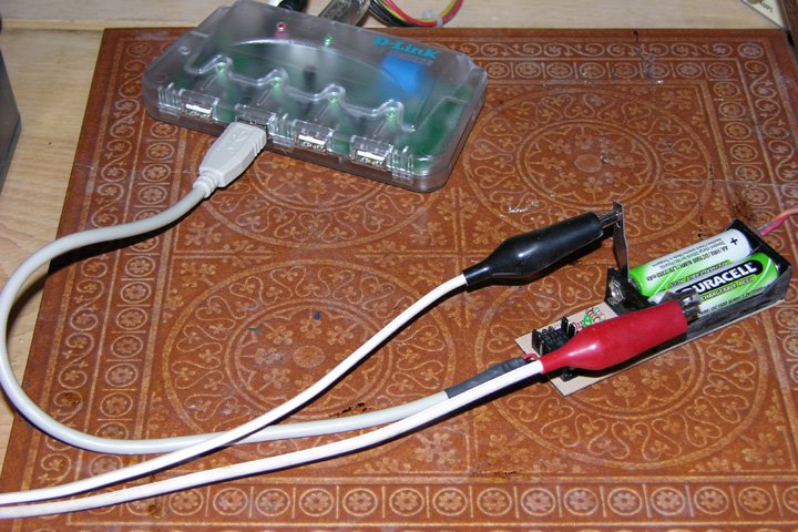 | |
| For initial tests, I used a USB hub for power. Para las pruebas iniciales, he usado un concentrador USB para la energía. A pair of #11 hobby knife blades between the cells and the contacts let me hook up a voltage monitor. Un par de # 11 hojas de cuchillo de la manía entre las células y los contactos me deja conectar un monitor de tensión. |
With the LED off, measure the voltage between GND and Vref (pin 3 of Z1). Con el apagado del LED, medir el voltaje entre GND y Vref (pin 3 del Z1). This should be approximately 2.37V. Esta debe ser de aproximadamente 2.37V. It can be a bit more or less depending on the exact supply voltage and the variation in resistor values. Puede ser un poco más o menos dependiendo de la tensión de alimentación exacta y la variación en los valores de resistencia. Also check the voltage at Vtmp (pin 2). También puedes ver el voltaje en Vtmp (pin 2). At room temperature, this should be in the range of 1.60V to 1.85V, depending on the temperature. A temperatura ambiente, esto debe estar en el rango de 1.60V a 1.85V, dependiendo de la temperatura.
Now insert a pair of matching AA NiMH cells, preferrably ones that are partially or fully discharged. Ahora insertar un par de juego de AA NiMH, de preferencia los que están parcial o completamente descargada. As soon as you insert the second cell, the LED should light up. Tan pronto como se inserta la segunda celda, el LED se iluminará. Measure the Vref voltage again; it should now be about 1.26V. Vtmp may also have changed a little bit, due to the supply voltage drop caused by the load placed on the power supply. Medir la tensión Vref nuevo, sino que ahora debe ser de 1.26V de suministro. Vtmp pueden también han cambiado poco un poco, debido a la tensión causada por la caída de la carga colocada en el poder.
The charger is now charging and the voltage at the battery terminals should be increasing. El cargador está ahora la carga y la tensión en los terminales de la batería debe estar aumentando. After a while, the rate of increase should slow down. Después de un tiempo, la tasa de crecimiento debe reducir la velocidad. As the cells reach about 75% charge, the rate of increase will speed up again. Como las células alcanzan el 75% de carga, la tasa de crecimiento se acelerará de nuevo. Finally, when the cells reach 100% charge, the voltage will start decreasing, and the cells will start to get warm. Por último, cuando las células llegar a 100% de carga, el voltaje empezará a decrecer, y las células comienzan a entrar en calor. 15 to 20 minutes later, the charger should turn off. 15 a 20 minutos más tarde, el cargador se debe apagar. If the cells get uncomfortably warm and the charger has not shut off, there's something wrong. Si las células se incómodamente caliente y el cargador no se ha apagado, hay algo mal.
It's also worth measuring the charge current. También vale la pena medir la corriente de carga. The easiest way to do this is to insert two thin conductive strips, such as brass shim, separated by an insulator, between one cell and a battery holder contact. La forma más sencilla de hacerlo es colocar dos tiras delgadas conductoras, como cuña de bronce, separados por un aislante, entre una célula y un contacto de la batería titular. Then connect an ammeter to the two strips, so that the charging current flows through the meter. A continuación, conecte un amperímetro a las dos bandas, por lo que la contabilización de los flujos de corriente a través del medidor. The meter should read somewhere between 450 and 490mA. El medidor debe leer en alguna parte entre 450 y 490mA. If it's any higher, you will be exceeding the USB current supply specification, since the charger itself uses an additional 10mA (primarily for the LED). Si te sirve de más, usted será superior a la especificación USB suministro de corriente, ya que el mismo utiliza un cargador de 10 mA adicionales (principalmente para el LED).
If the measured current, I , is too high or too low, replace R5 with a different value resistor according to the following formula: Si la corriente medida, yo, es demasiado alto o demasiado bajo, reemplace R5 con una resistencia de valor diferente de acuerdo con la siguiente fórmula:
R5 = 1.6 x I R5 = 1,6 x IUse the nearest standard value. Utilice el valor más próximo estándar. For example, if you measure a current of 510mA, replace R5 with an 820Ω resistor. Por ejemplo, si se mide una corriente de 510mA, reemplace R5 con una resistencia de 820Ω. If the measured current was 420mA, use a 680Ω resistor. Si la corriente medida se 420mA, utilice una resistencia de 680Ω.
Enclosure Recinto
At the time I wrote this, I had not yet constructed an enclosure for this circuit, but plan to do so in the near future, since the bare board is not robust enough to throw into the laptop bag when going on a trip. En el momento de escribir esto, no había construido todavía un recinto para este circuito, pero tienen previsto hacerlo en un futuro próximo, ya que la tarjeta desnuda no es lo suficientemente robusta como para tirar en la bolsa del ordenador portátil cuando se va de viaje. The enclosure will be made from 1/16" plastic or aircraft plywood for the sides and bottom, with a translucent plastic panel over the circuitry. The battery compartment will be left open. A strain relief will prevent the USB leads from breaking off where they attach to the board. For cooling, I plan to drill holes in the sides and top in the heatsink area. El recinto se hará a partir del 1 / 16 "de plástico o de madera contrachapada de aeronaves para los lados y fondo, con un panel de plástico transparente sobre el trazado de circuito. El compartimiento de la batería se deja abierta. Una descarga de tracción evitará que el USB conduce de ruptura en el que conectar a la placa. Para el enfriamiento, planeo hacer agujeros en los lados y la parte superior de la zona del disipador de calor.Using the Charger Uso del cargador
Using the charger is easy. El uso del cargador es fácil. Just plug it into a USB port and insert the two cells you want to charge. Sólo tiene que conectarlo a un puerto USB e inserte las dos celdas que desea cargar. When the LED extinguishes, charging is complete. Cuando el LED se apaga, la carga está completa. Approximate charge times are as follows: Tiempo aproximado de carga son los siguientes:| Cell Type Tipo de la célula | Charge Time Tiempo de carga |
|---|---|
| 700mAh NiCd 700mAh NiCd | 1.5h 1.5h |
| 1100mAh NiCd 1100mAh NiCd | 2.5h 2,5 h |
| 1600mAh NiMH 1600mAh NiMH | 3.5h 3.5h |
| 2000mAh NiMH 2000mAh NiMH | 4.5h 4.5h |
| 2500mAh NiMH 2500mAh NiMH | 5.5h 5.5h |
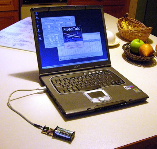 | |
| This charger, with a suitable enclosure, is ideal for use on trips, using a laptop to power the charger. Este cargador, con un recinto adecuado, es ideal para usar en viajes, con un ordenador portátil para alimentar el cargador. The laptop should be plugged in to avoid running down its battery. La computadora portátil debe estar conectado para evitar agotar la batería. |
When using this charger with any computer, make sure that the computer is not set to go into a power saving mode that turns off power to the USB ports. Al utilizar este cargador con cualquier computadora, asegúrese de que el equipo no esté configurado para entrar en un modo de ahorro de energía que convierte el suministro de energía a los puertos USB. If this happens, charging will stop, and the cells being charged will discharge. Si esto sucede, el proceso se detiene, y las células se está cargando la descarga. When using a laptop as a power source, it's best to plug in the laptop's power supply, since the charger uses a significant amount of power, and will probably take longer to complete than the laptop battery will last. Al utilizar un ordenador como fuente de energía, lo mejor es conectar la fuente de alimentación del portátil, ya que el cargador utiliza una cantidad significativa de energía, y probablemente llevará más tiempo en completarse que la batería del portátil va a durar.
If powering this charger from a USB hub, be sure to use a powered hub. Si accionar este cargador de un concentrador USB, asegúrese de usar un concentrador con alimentación. A non-powered hub will not be able to deliver enough current to the charger, since it must share the 500mA coming from the computer with the ports in the hub (typically four). Un concentrador sin alimentación eléctrica no será capaz de ofrecer suficiente corriente para el cargador, ya que deben compartir la 500mA procedentes de la computadora con los puertos en el centro (generalmente cuatro). The extra cable length also tends to reduce the voltage reaching the charger. La longitud del cable adicional también tiende a reducir la tensión que llega el cargador.
Charging AAA Cells Las células de carga AAA
If the springs in the battery holder are long enough, the charger can also be used to charge a pair of AAA cells. Si los muelles en el soporte de la batería son lo suficientemente largos, el cargador también puede ser utilizado para cargar un par de pilas AAA. However, it is then necessary to insert shims between the cells and the sides of the battery holder to ensure that the cells remain in contact with the thermistor. Sin embargo, es necesario entonces introducir cuñas entre las células y los lados del soporte de la batería para asegurarse de que las células permanecen en contacto con el termistor. Only charge modern AAA cells, having a capacity of 700mAh or more. Sólo las células de carga modernos AAA, con una capacidad de 700 mAh o más.Parts List Lista de piezas
Some parts can be obtained at Radio Shack, but larger electronic supply houses like Digi-Key are more likely to stock all the parts needed. Algunas partes se pueden obtener en Radio Shack, pero más grandes casas de suministros electrónicos como Digi-Key tienen más probabilidades de stock todas las piezas necesarias.| Part Parte | Description Descripción |
|---|---|
| R1 R1 | 56kΩ ¼W, 5% resistor 56kΩ ¼ W, 5% de resistencia |
| R2 R2 | 27kΩ ¼W, 5% resistor 27kΩ ¼ W, 5% de resistencia |
| R3 R3 | 22kΩ ¼W, 5% resistor 22kΩ ¼ W, 5% de resistencia |
| R4 R4 | 47kΩ ¼W, 5% resistor 47kΩ ¼ W, 5% de resistencia |
| R5 R5 | 750Ω ¼W, 5% resistor 750Ω ¼ W, 5% de resistencia |
| R6 R6 | 220Ω ¼W, resistor 220Ω ¼ W, resistencia |
| TR1 TR1 | 10kΩ @ 25°C thermistor, approx. 10 k @ 25 ° C termistor, aprox. 3.7%/C° NTC 3,7% / ° C NTC Radio Shack #271-110 (discontinued † ) Radio Shack # 271 hasta 110 (descontinuado †) |
| C1 C1 | 0.1µF 10V capacitor 0.1μF 10V condensador |
| Q1 Q1 | TIP32C PNP transistor, TO-220 case TIP32C transistor PNP, A-220 casos |
| Z1 Z1 | LM393 dual voltage comparator IC, DIP comparador LM393 doble voltaje del IC, DIP |
| LED1 LED1 | Red, green, or yellow LED, 10mA Rojo, verde o amarillo del LED, 10mA |
| Other Otros | 2-cell AA battery holder 2-celular titular de AA de la batería USB cable Cable USB Small heatsink disipador de calor pequeños |
Alternatively, you can use the resistor values below with the Vishay thermistor to raise the cut-off temperature back to 33°C, while lowering the turn-on temperature to 3°C (37°F). Alternativamente, puede utilizar la resistencia de los valores por debajo con el termistor Vishay para elevar la temperatura de corte de nuevo a 33 ° C, al tiempo que reduce el desvío de la temperatura de 3 ° C (37 ° F).
| Part Parte | Alternative Resistor Values to use with Alternativas de resistencia para su uso con valores Vishay #2381 640 54103 Thermistor Vishay # 2381 640 54103 termistor |
|---|---|
| R1 R1 | 82kΩ ¼W, 5% resistor 82kΩ ¼ W, 5% de resistencia |
| R2 R2 | 33kΩ ¼W, 5% resistor 33kΩ ¼ W, 5% de resistencia |
| R3 R3 | 27kΩ ¼W, 5% resistor 27kΩ ¼ W, 5% de resistencia |
| R4 R4 | 39kΩ ¼W, 5% resistor 39kΩ ¼ W, 5% de resistencia |